Sepetiniz
Sepetiniz boş


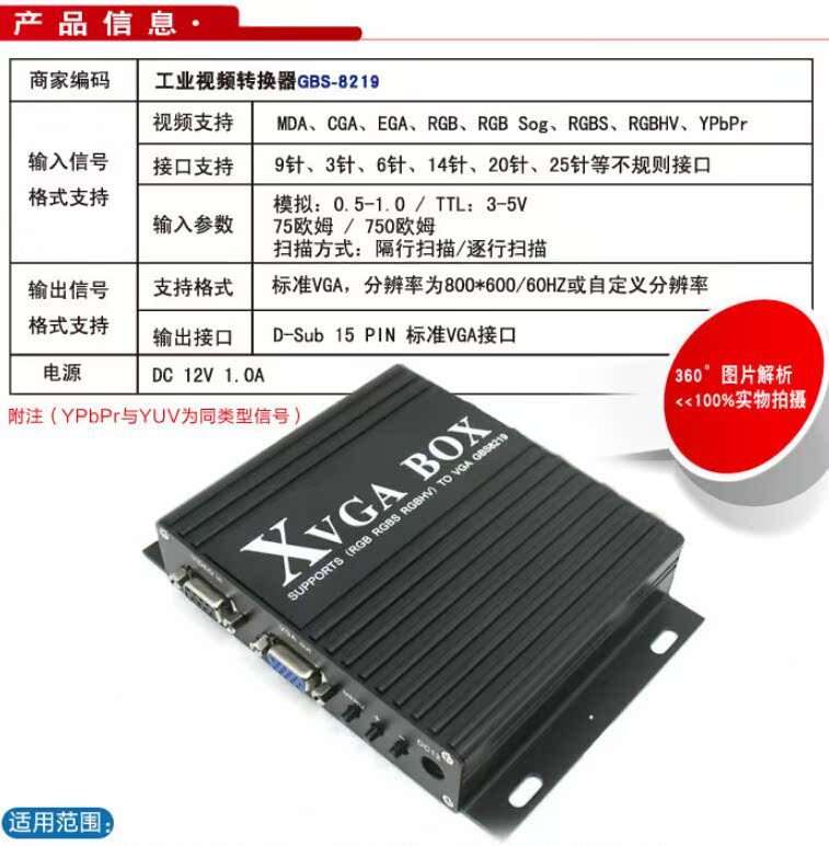
Printing machine/Bearing milling machine/Circuit board drilling machine/Glass edger Display maintenance GBS-8219 genuine
For more successful solutions for RGB to VGA industrial converter GBS-8219, please contact us

Product interface structure diagram

The above interface is introduced as follows:
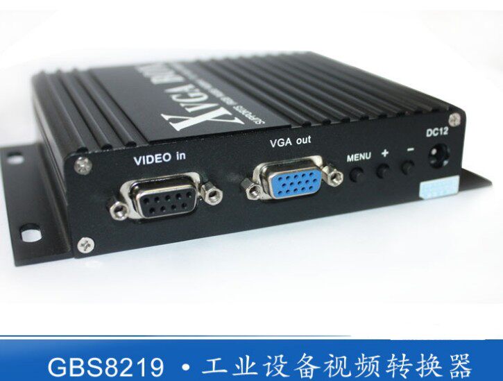
DC12V: Power input, DC 12V voltage, current 1A or above.
MENU, +, -: Device adjustment menu keys, +, - keys to move the cursor up and down or modify the value.
VGA OUT: Standard VGA signal output interface, directly connected to LCD or VGA devices.
VIDEO IN: 9-pin signal input interface, connecting the original signal output by industrial and other equipment.
V: field synchronization signal.
H/CS: line synchronization signal, or compound synchronization signal.
R/Pr: red signal, or color difference PR signal.
G/Y: Green signal, or Y signal with color difference.
B/Pb: Blue signal, or Pb signal with color difference.
RUN: Equipment operation indicator.
Among them, 9 pins or BNC mode input, you can choose one of them.
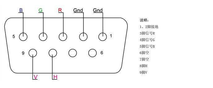
9-Pin signal input port definition
Video signal input method


GBS8219 Menu Item Definition

1. Horizontal position: This item can adjust the horizontal start position of the video display.
2. Horizontal size: This item can adjust the size of the video display width.
3. Vertical position: This item can adjust the vertical start position of the video display.
4. Vertical size: This item can adjust the size of the video display height.
5. Phase adjustment: This item can fine-tune the phase of the video source.
6. Video source type: This item is selected by the user to enter the video source type (RGB, or YUV). If the user selects the wrong video source, the video display color may be incorrect.
7. Synchronization signal: This item automatically recognizes the synchronization signal of the input video and can also be adjusted by the user.
8. Input impedance: This item is selected by the user to have an input impedance of 75 ohms or 750 ohms. If the input resistance is large, the brightness will be large.
9. Scanning method: This item allows the user to select whether the input video information is interlaced or progressive.
10. Exit and save: After the user adjusts all parameters, exit and save all parameters.
If you don't press any key for 11 or 15 seconds, the menu will automatically save the current parameters and exit. (The OSD menu will appear when there is no signal source input)
GBS 8219 Key operation definition
1. Enter the general settings menu: press the menu key once.
2. Enter the advanced settings menu: press and hold the menu button for 5 seconds.
3. Move the cursor down: press the + key.
4. Move the cursor up: press the - key.
5. Select the current item: press the menu key
6. Exit the current project: Press the menu key
7. Modify the selected item: + or - key.
GBS 8219 menu adjustment order
Step 1: After connecting the signal, if there is no display or the display color is incorrect, adjust the video source type item to be consistent with the input video signal type, and the color will be displayed normally. (Options are: YUV color difference, RGB (D) digital TTL signal, RGB (A) analog signal)
Step 2: The system can automatically identify the synchronization signal. If the image color display is normal after adjusting the first step, there is no need to manually adjust this item; if the image distortion occurs, you need to manually adjust the synchronization signal to be consistent with the synchronization type of the signal source, and the screen can be displayed normally.
Step 3: If the screen display is elongated and overflows to the bottom of the screen, adjust the scanning method to: Progressive; if the vertical position is adjusted to the maximum, the image display still only accounts for half of the display, then adjust the scanning method to: Interlaced.
Step 4: Adjust the horizontal position, horizontal size, vertical position, and vertical size items to a satisfactory position.
Step 5: Input impedance, choose the input impedance that matches the signal source, choose 750 ohms, which is relatively bright. If you choose 750 ohms to be all white, you should choose 75 ohms.
Step 6: Phase adjustment. If there is a slight wavy jitter up and down the image, you can adjust this to match the phase of the input signal.
Step 7: Save and exit. Save all parameters on the menu and exit.
Combo Up Savings Up To $1060+
The more you add, the more you'll save!
NewTouchBuff Official Store
Printing machine/Bearing milling machine/Circuit board drilling machine/Glass edger Display maintenance GBS-8219 genuine
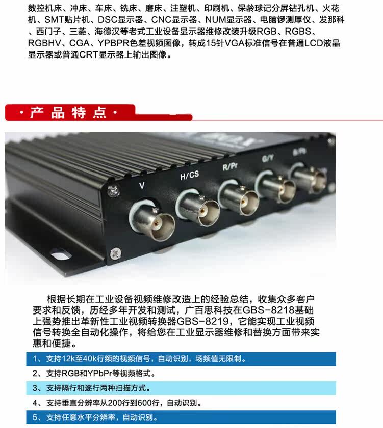
Stop Overpaying for Industrial Gear! As a direct supplier, we cut out middlemen to bring you premium industrial control products at unbeatable prices—PLC modules, replacement cables, industrial fans, touch glass, and more. Our industrial-grade products reduce maintenance costs by 30%, minimize downtime by 40%, and last 2x longer than cheap alternatives. Invest once, save for years—choose cost-effective, reliable gear that keeps your factory efficient and your budget in check. Shop now and enjoy the best value for your industrial procurement!
Estimated delivery between Temmuz 26 and Temmuz 28.
Price Match
We check our prices every day to ensure we can bring you the best price possible. In the unlikely case that you have found a cheaper price then please contact us on sales@seawens.com and we'll do our best to answer your query right away!
Multibuy Discounts
Planning to purchase multiple electrical appliances or household electronics?
We offer exclusive multibuy discounts with customised package pricing when you order two or more products together.
WhatsApp on (+86) 195 2767 5574 or visit our Multibuy Discounts page for full details and to request your tailored quote today.
Finance
We've partnered up with PayPal!
Why use PayPal?
✅ Safe and private, your bank info is well protected
✅ Official buyer protection, safe for your order
✅ Payment arrives instantly, we can ship immediately
✅ Easy to operate, no complicated bank procedures
✅ Much faster and simpler than TT wire transfer
How does it work?
- Add your purchase to cart
- Select PayPal or Credit Card at the checkout
- Complete PayPal application
- Compare any available finance options
Delivery Information
- Shipping TimeOrders will be shipped within 1–3 working days after payment is confirmed. Stock items can be arranged for shipment on the same day.
- Shipping MethodWe use international express such as DHL, FedEx, UPS, TNT and EMS.For bulk orders, we also support air freight and sea freight.
- Delivery Time
- International Express: About 3–7 working days to most countries
- Air Freight: About 7–15 working days
- Sea Freight: About 25–45 working days (depends on destination port)
- Tracking NumberOnce dispatched, we will send you the tracking number and shipping link immediately. You can check the shipment status online anytime.
- PackagingAll products are packed with anti-static bag, foam box and carton.Professional shockproof and moisture-proof packaging to ensure goods arrive in good condition.
- Customs & DutiesThe import tax and customs duty are borne by the buyer.We can declare a reasonable value to help you reduce customs tax.
- Delivery AddressPlease confirm your full delivery address, postcode and contact phone number correctly. We are not responsible for delivery delay caused by wrong address.
Flexible Delivery
We know that you expect your goods to be delivered promptly and efficiently. That’s why we have made it a priority at NewTouchBuff.com to deliver your goods as quickly as possible using our fast, efficient delivery service which comes direct to your home and is FREE for most items!
- We deliver seven days a week
- Standard deliveries are despatched via specialist carriers and are normally delivered within 3-5 working days.
- Express deliveries are dispatched same day (if ordered before 14:30) for delivery within 1-2 working days.
- For weekend deliveries, orders need to be placed by 14:30 on Friday.
- Larger Items are despatched using our team of specialist nationwide carriers. You will be contacted within 48 hours verifying your order and an estimated delivery date.
- Deliveries direct from manufacturers or suppliers can take a little longer but we will keep you informed and updated.
Focus on Reliability & Efficiency
Your Industrial Production Deserves the Best—Don’t Settle for Less!
Highly Stimulating
Hurry Up! Limited Stock Alert for Industrial Control Essentials!
For more successful solutions for RGB to VGA industrial converter GBS-8219, please contact us
Product interface structure diagram
The above interface is introduced as follows:
DC12V: Power input, DC 12V voltage, current 1A or above.
MENU, +, -: Device adjustment menu keys, +, - keys to move the cursor up and down or modify the value.
VGA OUT: Standard VGA signal output interface, directly connected to LCD or VGA devices.
VIDEO IN: 9-pin signal input interface, connecting the original signal output by industrial and other equipment.
V: field synchronization signal.
H/CS: line synchronization signal, or compound synchronization signal.
R/Pr: red signal, or color difference PR signal.
G/Y: Green signal, or Y signal with color difference.
B/Pb: Blue signal, or Pb signal with color difference.
RUN: Equipment operation indicator.
Among them, 9 pins or BNC mode input, you can choose one of them.
9-Pin signal input port definition
Video signal input method
GBS8219 Menu Item Definition
1. Horizontal position: This item can adjust the horizontal start position of the video display.
2. Horizontal size: This item can adjust the size of the video display width.
3. Vertical position: This item can adjust the vertical start position of the video display.
4. Vertical size: This item can adjust the size of the video display height.
5. Phase adjustment: This item can fine-tune the phase of the video source.
6. Video source type: This item is selected by the user to enter the video source type (RGB, or YUV). If the user selects the wrong video source, the video display color may be incorrect.
7. Synchronization signal: This item automatically recognizes the synchronization signal of the input video and can also be adjusted by the user.
8. Input impedance: This item is selected by the user to have an input impedance of 75 ohms or 750 ohms. If the input resistance is large, the brightness will be large.
9. Scanning method: This item allows the user to select whether the input video information is interlaced or progressive.
10. Exit and save: After the user adjusts all parameters, exit and save all parameters.
If you don't press any key for 11 or 15 seconds, the menu will automatically save the current parameters and exit. (The OSD menu will appear when there is no signal source input)
GBS 8219 Key operation definition
1. Enter the general settings menu: press the menu key once.
2. Enter the advanced settings menu: press and hold the menu button for 5 seconds.
3. Move the cursor down: press the + key.
4. Move the cursor up: press the - key.
5. Select the current item: press the menu key
6. Exit the current project: Press the menu key
7. Modify the selected item: + or - key.
GBS 8219 menu adjustment order
Step 1: After connecting the signal, if there is no display or the display color is incorrect, adjust the video source type item to be consistent with the input video signal type, and the color will be displayed normally. (Options are: YUV color difference, RGB (D) digital TTL signal, RGB (A) analog signal)
Step 2: The system can automatically identify the synchronization signal. If the image color display is normal after adjusting the first step, there is no need to manually adjust this item; if the image distortion occurs, you need to manually adjust the synchronization signal to be consistent with the synchronization type of the signal source, and the screen can be displayed normally.
Step 3: If the screen display is elongated and overflows to the bottom of the screen, adjust the scanning method to: Progressive; if the vertical position is adjusted to the maximum, the image display still only accounts for half of the display, then adjust the scanning method to: Interlaced.
Step 4: Adjust the horizontal position, horizontal size, vertical position, and vertical size items to a satisfactory position.
Step 5: Input impedance, choose the input impedance that matches the signal source, choose 750 ohms, which is relatively bright. If you choose 750 ohms to be all white, you should choose 75 ohms.
Step 6: Phase adjustment. If there is a slight wavy jitter up and down the image, you can adjust this to match the phase of the input signal.
Step 7: Save and exit. Save all parameters on the menu and exit.
Authencity Guaranteed
We only sell authentic products from verified brand partners and retail partners globally.
Maintenance, Repair And Replacement


$750.00 USD
Receives in 5 days.


$250.95 USD
Receives in 5 days.

$449.95 USD
Receives in 5 days.


$179.95 USD
Receives in 5 days.


$189.95 USD
Receives in 5 days.


$204.95 USD
Receives in 5 days.


$229.95 USD
Receives in 5 days.


$219.95 USD
Receives in 5 days.


Receives in 5 days.


$109.95 USD
Receives in 5 days.


Receives in 5 days.


Receives in 5 days.


- Bir seçim yapmak tüm sayfanın yenilenmesine neden olur.
- Yeni pencerede açılır.